
Monday, November 29, 2010
shock wave

A shock wave (also called shock front or simply "shock") is a type of propagating disturbance. Like an ordinary wave, it carries energy and can propagate through a medium (solid, liquid, gas or plasma) or in some cases in the absence of a material medium, through a field such as the electromagnatic field. Shock waves are characterized by an abrupt, nearly discontinuous change in the characteristics of the medium.Across a shock there is always an extremely rapid rise in pressure,temperature and density of the flow. In supersonic flows, expansion is achieved through an expansion fan. A shock wave travels through most media at a higher speed than an ordinary wave.
Unlike solitons (another kind of nonlinear wave), the energy of a shock wave dissipates relatively quickly with distance. Also, the accompanying expansion wave approaches and eventually merges with the shock wave, partially cancelling it out. Thus the sonic boom associated with the passage of a supersonic aircraft is the sound wave resulting from the degradation and merging of the shock wave and the expansion wave produced by the aircraft.
When a shock wave passes through matter, the total energy is preserved but the energy which can be extracted as work decreases and entropy increases. This, for example, creates additional drag force on aircraft with shocks.
Detached shock

shadowgraph of the detached shock on a bullet in supersonic flight, published by Ernst Mach in 1887.
- These shocks are curved, and form a small distance in front of the body. Directly in front of the body, they stand at 90 degrees to the oncoming flow, and then curve around the body. Detached shocks allow the same type of analytic calculations as for the attached shock, for the flow near the shock. They are a topic of continuing interest, because the rules governing the shock's distance ahead of the blunt body are complicated, and are a function of the body's shape. Additionally, the shock standoff distance varies drastically with the temperature for a non-ideal gas, causing large differences in the heat transfer to the thermal protection system of the vehicle. See the extended discussion on this topic at atmospheric reentry. These follow the "strong-shock" solutions of the analytic equations, meaning that for some oblique shocks very close to the deflection angle limit, the downstream Mach number is subsonic. See also bow shock or oblique shock
- Such a shock occurs when the maximum deflection angle is exceeded. A detached shock is commonly seen on blunt bodies, but may also be seen on sharp bodies at low Mach numbers.
- Examples: Space return vehicles (Apollo, Space shuttle), bullets, the boundary (Bow shock) of a magnetosphere. The name "bow shock" comes from the example of a bow wave, the detached shock formed at the bow (front) of a ship or boat moving through water, whose slow surface wave speed is easily exceeded (see ocean surface wave).
Attached shock
- These shocks appear as "attached" to the tip of a sharp body moving at supersonic speeds.
- Examples: Supersonic wedges and cones with small apex angles
- The attached shock wave is a classic structure in aerodynamics because, for a perfect gas and inviscid flow field, an analytic solution is available, such that the pressure ratio, temperature ratio, angle of the wedge and the downstream Mach number can all be calculated knowing the upstream Mach number and the shock angle. Smaller shock angles are associated with higher upstream Mach numbers, and the special case where the shock wave is at 90 degrees to the oncoming flow (Normal shock), is associated with a Mach number of one. These follow the "weak-shock" solutions of the analytic equations.
Wednesday, November 24, 2010
Forces on an Airplane
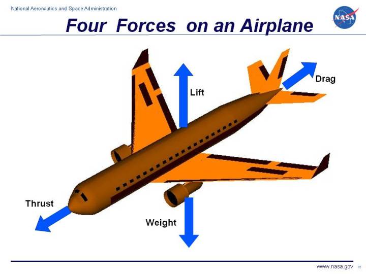
A force may be thought of as a push or pull in a specific direction. A force is a vector quantity so a force has both a magnitude and a direction. When describing forces, we have to specify both the magnitude and the direction. This slide shows the forces that act on an airplane in flight.
Weight
Weight is a force that is always directed toward the center of the earth. The magnitude of the weight depends on the mass of all the airplane parts, plus the amount of fuel, plus any payload on board (people, baggage, freight, etc.). The weight is distributed throughout the airplane. But we can often think of it as collected and acting through a single point called the center of gravity. In flight, the airplane rotates about the centre of gravity.
Weight is a force that is always directed toward the center of the earth. The magnitude of the weight depends on the mass of all the airplane parts, plus the amount of fuel, plus any payload on board (people, baggage, freight, etc.). The weight is distributed throughout the airplane. But we can often think of it as collected and acting through a single point called the center of gravity. In flight, the airplane rotates about the centre of gravity.
Flying encompasses two major problems; overcoming the weight of an object by some opposing force, and controlling the object in flight. Both of these problems are related to the object's weight and the location of the center of gravity. During a flight, an airplane's weight constantly changes as the aircraft consumes fuel. The distribution of the weight and the center of gravity also changes. So the pilot must constantly adjust the controls to keep the airplane balanced, or trimmed.
Lift
To overcome the weight force, airplanes generate an opposing force called lift. Lift is generated by the motion of the airplane through the air and is an aerodynamic force "Aero" stands for the air, and "dynamic" denotes motion. Lift is directedperpendicular to the flight direction. The magnitude of the lift depends on several factors including the shape, size, and velocity of the aircraft. As with weight, each part of the aircraft contributes to the aircraft lift force. Most of the lift is generated by the wings. Aircraft lift acts through a single point called the centre of pressure. The center of pressure is defined just like the center of gravity, but using the pressure distribution around the body instead of the weight distribution.
To overcome the weight force, airplanes generate an opposing force called lift. Lift is generated by the motion of the airplane through the air and is an aerodynamic force "Aero" stands for the air, and "dynamic" denotes motion. Lift is directedperpendicular to the flight direction. The magnitude of the lift depends on several factors including the shape, size, and velocity of the aircraft. As with weight, each part of the aircraft contributes to the aircraft lift force. Most of the lift is generated by the wings. Aircraft lift acts through a single point called the centre of pressure. The center of pressure is defined just like the center of gravity, but using the pressure distribution around the body instead of the weight distribution.
The distribution of lift around the aircraft is important for solving the control problem. Aerodynamic surfaces are used to control the aircraft in roll, pitch, and yaw.
Drag
As the airplane moves through the air, there is another aerodynamic force present. The air resists the motion of the aircraft and the resistance force is called drag. Drag is directed along and opposed to the flight direction. Like lift, there are many factors that affect the magnitude of the drag force including the shape of the aircraft, the "stickiness" of the air, and the velocity of the aircraft. Like lift, we collect all of the individual components' drags and combine them into a single aircraft drag magnitude. And like lift, drag acts through the aircraft center of pressure.
As the airplane moves through the air, there is another aerodynamic force present. The air resists the motion of the aircraft and the resistance force is called drag. Drag is directed along and opposed to the flight direction. Like lift, there are many factors that affect the magnitude of the drag force including the shape of the aircraft, the "stickiness" of the air, and the velocity of the aircraft. Like lift, we collect all of the individual components' drags and combine them into a single aircraft drag magnitude. And like lift, drag acts through the aircraft center of pressure.
Thrust
To overcome drag, airplanes use a propulsion system to generate a force called thrust. The direction of the thrust force depends on how the engines are attached to the aircraft. In the figure shown above, two turbine engines are located under the wings, parallel to the body, with thrust acting along the body centerline. On some aircraft, such as the Harrier, the thrust direction can be varied to help the airplane take off in a very short distance. The magnitude of the thrust depends on many factors associated with the propulsion system including the type of engine, the number of engines, and the throttle setting.
To overcome drag, airplanes use a propulsion system to generate a force called thrust. The direction of the thrust force depends on how the engines are attached to the aircraft. In the figure shown above, two turbine engines are located under the wings, parallel to the body, with thrust acting along the body centerline. On some aircraft, such as the Harrier, the thrust direction can be varied to help the airplane take off in a very short distance. The magnitude of the thrust depends on many factors associated with the propulsion system including the type of engine, the number of engines, and the throttle setting.
For jet engines, it is often confusing to remember that aircraft thrust is a reaction to the hot gas rushing out of the nozzle. The hot gas goes out the back, but the thrust pushes towards the front. Action <--> reaction is explained by Newton's Third law of motion.
The motion of the airplane through the air depends on the relative strength and direction of the forces shown above. If the forces are balanced, the aircraft cruises at constant velocity. If the forces are unbalanced, the aircraft accelerates in the direction of the largest force.
Note that the job of the engine is just to overcome the drag of the airplane, not to lift the airplane. A 1 million pound airliner has 4 engines that produce a grand total of 200,000 of thrust. The wings are doing the lifting, not the engines. In fact, there are some aircraft, called gliders that have no engines at all, but fly just fine. Some external source of power has to be applied to initiate the motion necessary for the wings to produce lift. But during flight, the weight is opposed by both lift and drag. Paper airplanes are the most obvious example, but there are many kinds of gliders. Some gliders are piloted and are towed aloft by a powered aircraft, then cut free to glide for long distances before landing. During reentry and landing, the Space Shuttle is a glider; the rocket engines are used only to loft the Shuttle into space.
You can view a short movie of "Orville and Wilbur Wright" explaining how the four forces of weight, lift, drag and thrust affected the flight of their aircraft. The movie file can be saved to your computer and viewed as a Podcast on your podcast player.
sonic boom

A sonic boom is the sound associated with the shock waves created by the supersonic flight of an aircraft. Sonic booms generate enormous amounts of sound energy, sounding much like an explosion. The crack of a supersonic bullet passing overhead is an example of a sonic boom in miniature.
Causes

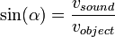
When an object passes through the air, it creates a series of pressure waves in front of it and behind it, similar to the bow and stern waves created by a boat. These waves travel at the speed of sound, and as the speed of the object increases, the waves are forced together, or compressed, because they cannot "get out of the way" of each other, eventually merging into a single shock wave at the speed of sound. This critical speed is known as Mach 1 and is approximately 1,225 km/h (761 mph) at sea level and 20 °C (68 °F). In smooth flight, the shock wave starts at the nose of the aircraft and ends at the tail. Because directions around the aircraft's direction of travel are equivalent, the shock forms a Mach cone with the aircraft at its tip. The half-angle (between direction of flight and the shock wave) α is given by
 ,
,
where  is the plane's Mach number. So the faster it goes, the finer, (more pointed) the cone.
is the plane's Mach number. So the faster it goes, the finer, (more pointed) the cone.There is a rise in pressure at the nose, decreasing steadily to a negative pressure at the tail, followed by a sudden return to normal pressure after the object passes. This "overpressure profile" is known as an N-wave because of its shape. The "boom" is experienced when there is a sudden change in pressure, so the N-wave causes two booms, one when the initial pressure rise from the nose hits, and another when the tail passes and the pressure suddenly returns to normal. This leads to a distinctive "double boom" from supersonic aircraft. When maneuvering, the pressure distribution changes into different forms, with a characteristic U-wave shape.
Since the boom is being generated continually as long as the aircraft is supersonic, it fills out a narrow path on the ground following the aircraft's flight path, a bit like an unrolling red carpet and hence known as the "boom carpet". Its width depends on the altitude of the aircraft. The distance from the point on the ground where the boom is heard to the aircraft depends on its altitude and the angle α.
For today's supersonic aircraft in normal operating conditions, the peak overpressure varies from less than one pound per square foot to about 10 pounds per square foot (50 to 500 Pa) for a N-wave boom. Peak overpressures for U-waves are amplified two to five times the N-wave, but this amplified overpressure impacts only a very small area when compared to the area exposed to the rest of the sonic boom. The strongest sonic boom ever recorded was 144 pounds per square foot (7,000 Pa) and it did not cause injury to the researchers who were exposed to it. The boom was produced by a F-4 flying just above the speed of sound at an altitude of 100 feet. In recent tests, the maximum boom measured during more realistic flight conditions was 21 pounds per square foot (1,010 Pa). There is a probability that some damage — shattered glass for example — will result from a sonic boom. Buildings in good repair should suffer no damage by pressures of 11 pounds per square foot or less. And, typically, community exposure to sonic boom is below two pounds per square foot. Ground motion resulting from sonic boom is rare and is well below structural damage thresholds accepted by the U.S.Bureau of Mines and other agencies.
The power, or volume, of the shock wave is dependent on the quantity of air that is being accelerated, and thus the size and shape of the aircraft. As the aircraft increases speed the shock cone gets tighter around the craft and becomes weaker to the point that at very high speeds and altitudes no boom is heard. The "length" of the boom from front to back is dependent on the length of the aircraft to a factor of 3:2. Longer aircraft therefore "spread out" their booms more than smaller ones, which leads to a less powerful boom which has a less "spread out" boom.
Several smaller shock waves can, and usually do, form at other points on the aircraft, primarily any convex points or curves, the leading wing edge and especially the inlet to engines. These secondary shockwaves are caused by the air being forced to turn around these convex points, which generates a shock wave in supersonic flow.
The later shock waves are somewhat faster than the first one, travel faster and add to the main shockwave at some distance away from the aircraft to create a much more defined N-wave shape. This maximizes both the magnitude and the "rise time" of the shock which makes the boom seem louder. On most designs the characteristic distance is about 40,000 feet (12,000 m), meaning that below this altitude the sonic boom will be "softer". However, the drag at this altitude or below makes supersonic travel particularly inefficient, which poses a serious problem.
aircraft control surfaces

Aircraft flight control surfaces allow a pilot to adjust and control the aircraft's flight attitude.
Development of an effective set of flight controls was a critical advance in the development of aircraft. Early efforts at fixed-wing aircraft design succeeded in generating sufficient lift to get the aircraft off the ground, but once aloft, the aircraft proved uncontrollable, often with disastrous results. The development of effective flight controls is what allowed stable flight.
This article describes the control surfaces used on a fixed wing aircraft of conventional design. Other fixed wing aircraft configurations may use different control surfaces but the basic principles remain. The controls (stick and rudder) for rotary wing aircraft (helicopter or autogyro) accomplish the same motions about the three axes of rotation, but manipulate the rotating flight controls (main rotor disk and tail rotor disk) in a completely different manner.
Development
The Wright brothers are credited with developing the first practical control surfaces. It is a main part of their patent on flying. Unlike modern control surfaces they used wing wrapping. In an attempt to circumvent the Wright patent, Glen Curtis made hinged control surfaces. Hinged control surfaces have the advantage of not causing stresses that are a problem of wing warping and are easier to build into structures.
Axes of motion

An aircraft is free to rotate around three axes which are perpendicular to each other and intersect at its center of gravity (CG). To control position and direction a pilot must be able to control rotation about each of them.
Lateral axis
The lateral axis passes through the plane from wingtip to wingtip. Rotation about this axis is called pitch. Pitch changes the vertical direction the aircraft's nose is pointing. The elevators are the primary control of pitch.
Longitudinal axis
The longitudinal axis passes through the aircraft from nose to tail. Rotation about this axis is called roll. Rolling motion changes the orientation of the aircraft's wings with respect to the downward force of gravity. The pilot changes bank angle by increasing the lift on one wing and decreasing it on the other. This differential lift causes bank rotation around the longitudinal axis. The ailerons are the primary control of bank. The rudder also has a secondary effect on bank.
Vertical axis
The vertical axis passes through an aircraft from top to bottom. Rotation about this axis is called yaw. Yaw changes the direction the aircraft's nose is pointing, left or right. The primary control of yaw is with the rudder. Ailerons also have a secondary effect on yaw.
It is important to note that these axes move with the aircraft, and change relative to the earth as the aircraft moves. For example, for an aircraft whose left wing is pointing straight down, its "vertical" axis is parallel with the ground, while its "lateral" axis is perpendicular to the ground.
Main control surfaces
The main control surfaces of a fixed-wing aircraft are attached to the airframe on hinges or tracks so they may move and thus deflect the air stream passing over them. This redirection of the air stream generates an unbalanced force to rotate the plane about the associated axis.
Ailerons

Ailerons are mounted on the trailing edge of each wing near the wingtips, and move in opposite directions. When the pilot moves the stick left, or turns the wheel counter-clockwise, the left aileron goes up and the right aileron goes down. A raised aileron reduces lift on that wing and a lowered one increases lift, so moving the stick left causes the left wing to drop and the right wing to rise. This causes the aircraft to roll to the left and begin to turn to the left. Centering the stick returns the ailerons to neutral maintaining the bank angle. The aircraft will continue to turn until opposite aileron motion returns the bank angle to zero to fly straight.
Elevator
An elevator is mounted on the trailing edge of the horizontal stbilizer on each side of the fin in the tail. They move up and down together. When the pilot pulls the stick backward, the elevators go up. Pushing the stick forward causes the elevators to go down. Raised elevators push down on the tail and cause the nose to pitch up. This makes the wings fly at a higher angle of attack which generates more lift and more drag. Centering the stick returns the elevators to neutral and stops the change of pitch. Many aircraft use a stabilator — a moveable horizontal stabilizer — in place of an elevator. Some aircraft, such as an MD-80, use a servo tab within the elevator surface to aerodynamically move the main surface into position. The direction of travel of the control tab will thus be in a direction opposite to the main control surface. It is for this reason that an MD-80 tail looks like it has a 'split' elevator system.
Rudder
The rudder is typically mounted on the trailing edge of the fin, part of the empennage. When the pilot pushes the left pedal, the rudder deflects left. Pushing the right pedal causes the rudder to deflect right. Deflecting the rudder right pushes the tail left and causes the nose to yaw to the right. Centering the rudder pedals returns the rudder to neutral and stops the yaw.
Secondary effects of controls
Ailerons
The ailerons primarily control roll. Whenever lift is increased, induced drag is also increased. When the stick is moved left to roll the aircraft to the left, the right aileron is lowered which increases lift on the right wing and therefore increases induced drag on the right wing. Using ailerons causes adverse yaw, meaning the nose of the aircraft yaws in a direction opposite to the aileron application. When moving the stick to the left to bank the wings, adverse yaw moves the nose of the aircraft to the right. Adverse yaw is more pronounced for light aircraft with long wings, such as gliders. It is counteracted by the pilot with the rudder. Differential ailerons are ailerons which have been rigged such that the downgoing aileron deflects less than the upward-moving one, reducing adverse yaw.
Rudder
Using the rudder causes one wing to move forward faster than the other. Increased speed means increased lift, and hence rudder use causes a roll effect. Also, since rudders generally extend above the aircraft's center of gravity, a torque is imparted to the aircraft resulting in an adverse bank. Pushing the rudder to the right not only pulls the tail to the left and the nose to the right, but it also "spins" the aircraft as if a left turn were going to be made. Out of all the control inputs, rudder input creates the greatest amount of adverse effect. For this reason ailerons and rudder are generally used together on light aircraft: when turning to the left, the control column is moved left, and adequate left rudder is applied.
Turning the aircraft
Unlike a boat, turning an aircraft is not normally carried out with the rudder. With aircraft, the turn is caused by the horizontal component of lift. The lifting force, perpendicular to the wings of the aircraft, is tilted in the direction of the intended turn by rolling the aircraft into the turn. As the bank angle is increased the lifting force, which was previously acting only in the vertical, is split into two components: One acting vertically and one acting horizontally.
If the total lift is kept constant, the vertical component of lift will decrease. As the weight of the aircraft is unchanged, this would result in the aircraft descending if not countered. To maintain level flight requires increased positive (up) elevator to increase the angle of attack, increase the total lift generated and keep the vertical component of lift equal with the weight of the aircraft. This cannot continue indefinitely. The wings can only generate a finite amount of lift at a given air speed. As the load factor (commonly called G loading) is increased an accelerated aerodynamic stall will occur, even though the aircraft is above its 1G stall speed.
The total lift (load factor) required to maintain level flight is directly related to bank angle. This means that for a given airspeed, level flight can only be maintained up to a certain given angle of bank. Beyond this angle of bank, the aircraft will suffer an accelerated stall if the pilot attempts to generate enough lift to maintain level flight.
Alternate main control surfaces
Some aircraft configurations have non-standard primary controls. For example instead of elevators at the back of the stabilizers, the entire tailplane may change angle. Some aircraft have a tail in the shape of a V, and the moving parts at the back of those combine the functions of elevators and rudder. Delta wing aircraft may have "elevons" at the back of the wing, which combine the functions of elevators and ailerons.
Secondary control surfaces

Spoilers
On low drag aircraft like sailplanes, spoilers are used to disrupt airflow over the wing and greatly increase the amount of drag. This allows a glider pilot to lose altitude without gaining excessive airspeed. Spoilers are sometimes called "lift dumpers". Spoilers that can be used asymmetrically are called spoilerons and are able to affect an aircraft's roll.
Flaps
Flaps are mounted on the trailing edge of each wing on the inboard section of each wing (near the wing roots). They are deflected down to increase the effective curvature of the wing. Flaps raise the aximum Lift Coefficient of the aircraft and therefore reduce its stalling speed. They are used during low speed, high angle of attack flight including take-off and descent for landing. Some aircraft are equipped with "flapperons", which are more commonly called "inboard ailerons". These devices function primarily as ailerons, but on some aircraft, will "droop" when the flaps are deployed, thus acting as both a flap and a roll-control inboard aileron.
Slats
Slats, also known as Leading Edge Devices, are extensions to the front of a wing for lift augmentation, and are intended to reduce the stalling speed by altering the airflow over the wing. Slats may be fixed or retractable - fixed slats (e.g. as on the Fieseler Fi 156 storch) give excellent slow speed and STOL capabilities, but compromise higher speed performance. Retractable slats, as seen on most airliners, provide reduced stalling speed for take-off and landing, but are retracted for cruising.
Air brakes
Air brakes, also called spoilers, are used to increase drag. On a typical airliner, for example, the spoilers are a series of panels on the upper surface of the wing which deploy upwards to disrupt airflow over the wing, thus adding drag. The number of panels that deploy, as well as the degree to which they deploy, depends on the regime of flight in which they are used. For example, if a pilot must descend quickly without increasing speed, he may select a speed brake setting for the desired effect. In such a case, only certain spoiler panels will deploy to create the most efficient reduction in speed without overstressing the wing. On most airliners, spoiler panels on the wings mix with aileron inputs to enhance roll control. For example, a left bank will engage the ailerons as well as deploy certain spoiler panels on the down-going wing. Ground spoilers are essentially similar to flight spoilers, except that they deploy upon touchdown on the runway, and include all spoiler panels for maximum "lift dump". After touchdown, the ground spoilers deploy, and "dump" the lift generated by the wings, thus placing the aircraft's weight on the wheels, which accomplish the vast majority of braking after touchdown. Most jet airliners also have a thrust reverser, which simply deflects exhaust from the engines forward, helping to slow the aircraft down.
Other control surfaces
Trim controls
Trimming controls allow a pilot to balance the lift and drag being produced by the wings and control surfaces over a wide range of load and airspeed. This reduces the effort required to adjust or maintain a desired flight attitude.
Elevator trim
Elevator trim balances the control force necessary to maintain the aerodynamic down force on the tail. Whilst carrying out certain flight exercises, a lot of trim could be required to maintain the desired angle of attack. This mainly applies to slow flight, where maintaining a nose-up attitude requires a lot of trim. Elevator trim is correlated with the speed of the airflow over the tail, thus airspeed changes to the aircraft require re-trimming. An important design parameter for aircraft is the stability of the aircraft when trimmed for level flight. Any disturbances such as gusts or turbulence will be damped over a short period of time and the aircraft will return to its level flight trimmed airspeed.
Trimming tail plane
Except for very light aircraft, trim tabs on elevators are unable to provide the force and range of motion desired. To provide the appropriate trim force the entire horizontal tail plane is made adjustable in pitch. This allows the pilot to select exactly the right amount of positive or negative lift from the tail plane while reducing drag from the elevators.
Control horn
A control horn is a section of control surface which projects ahead of the pivot point. It generates a force which tends to increase the surface's deflection thus reducing the control pressure experienced by the pilot. Control horns may also incorporate a counterweight which helps to balance the control and prevent it from "fluttering" in the airstream. Some designs feature separate anti-flutter weights.
Spring trim
In the simplest cases trimming is done by a mechanical spring (or bungee) which adds appropriate force to augment the pilot's control input. The spring is usually connected to an elevator trim lever to allow the pilot to set the spring force applied.
Rudder and aileron trim
Trim often does not only apply to the elevator, as there is also trim for the rudder and ailerons in larger aircraft. The use of this is to counter the effects of slip stream, or to counter the effects of the centre of gravity being to one side. This can be caused by a larger weight on one side of the aircraft compared to the other, such as when one fuel tank has a lot more fuel in it than the other.
Subscribe to:
Posts (Atom)